

-18x16.jpg)


Login or create an account
CloseReturning Customer
I am a returning customer
Login or create an account
CloseRegister Account
If you already have an account with us, please login at the login form.
Your Account Has Been Created!
Thank you for registering with CNC Egy!
You will be notified by e-mail once your account has been activated by the store owner.
If you have ANY questions about the operation of this online shop, please contact the store owner.
Account Logout
You have been logged off your account. It is now safe to leave the computer.
Your shopping cart has been saved, the items inside it will be restored whenever you log back into your account.
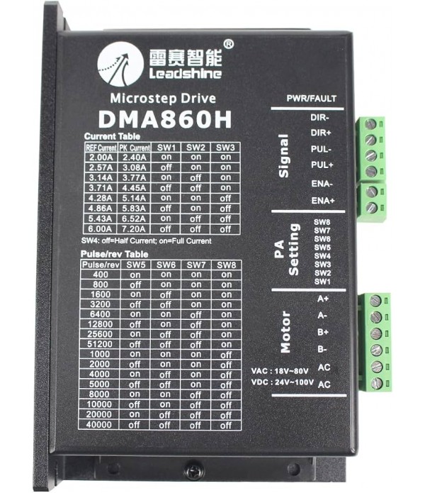
Leadshine DMA860H 7.2A DRIVER
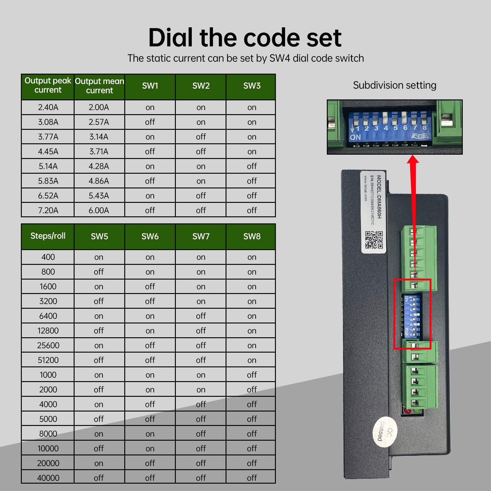
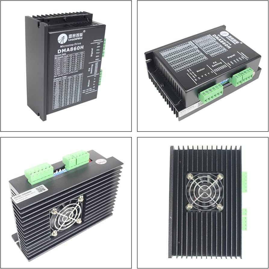
Product descriptionLeadshine DMA860H CNC Stepper Motor Driver Controller 18-80V AC/24-100V DC2.0A-7.2A, 400-51200 Microstep, 200KHz,Differential/Single/Pulse/Direction Input For Nema23/Nema24/Nema34 CNC Router MachineAbout this itemModel: DMA860H Driver; Voltage input: 18-80VAC; Current: 2.0A-7.2A,r..
Product description
Leadshine DMA860H CNC Stepper Motor Driver Controller 18-80V AC/24-100V DC
2.0A-7.2A, 400-51200 Microstep, 200KHz,Differential/Single/Pulse/Direction Input For Nema23/Nema24/Nema34 CNC Router Machine
About this item
- Model: DMA860H Driver; Voltage input: 18-80VAC; Current: 2.0A-7.2A,resolution: 0.1A; Microstep: 400-51200 ppr; Signal input: differential/single end,pulse/direction or double pulse; Pulse response frequency: 200KHz
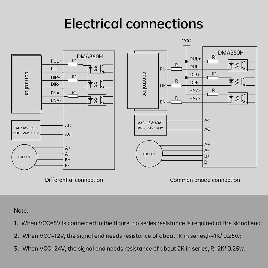
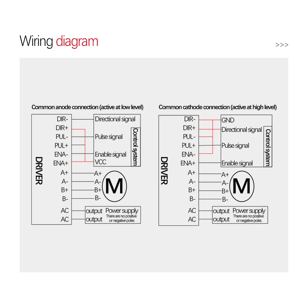
- Product Features: DMA860H The driver adopts differential interface circuit applicable to differential signal, single-terminal common negative and common positive interfaces, built-in high-speed optocoupler, allowing the reception of long line driver, collector open circuit and PNP output circuit signals
- Direction signal: High/low level signal. To ensure reliable commutation, the direction signal should be established at least five microns before the pulse signal. The initial running direction of the motor is related to the wiring of the motor. Interchanging any phase windings such as A+, A- switching can change the initial running direction of the motor, DIR- 4-5V at high voltage and 0-0.5V at low voltage
- Pulse control signal: The pulse rising edge is effective; PUL- 4-5V at high voltage and 0-0.5V at low voltage. To reliably respond to pulse signals, the pulse width should be greater than 1.2 microns. Series resistance is required if +12V or +24V is used
- Suitable motor: Can drive 4, 6 and 8-wire two-phase stepping motor,fit for Nema23 Nema34 Nema42 Stepper Motor;Also suitable for various small and medium-sized automation equipment and instruments, such as engraving machines, cutting machines, marking machines, engraving machines, plotters, CNC machine tools, automatic assembly equipment etc