


-18x16.jpg)


Login or create an account
CloseReturning Customer
I am a returning customer
Login or create an account
CloseRegister Account
If you already have an account with us, please login at the login form.
Your Account Has Been Created!
Thank you for registering with CNC Egy!
You will be notified by e-mail once your account has been activated by the store owner.
If you have ANY questions about the operation of this online shop, please contact the store owner.
Account Logout
You have been logged off your account. It is now safe to leave the computer.
Your shopping cart has been saved, the items inside it will be restored whenever you log back into your account.

JKBLD300--300W BLDC driver
48V Brushless DC Motor Driver BLD-300B 18-50VDC 300W BLDC Motor controller
Features
Type: BLDC motor driver Power: 300W Environment temperature: -10℃—50℃ Input Voltage: +18—+50VDC Output Current: 15A—35A Suitable Motor Speed: 0-20000Rpm Hall Sensor Voltage: 4.5V—5.5V External Potentiometer: 10kΩ
JKBLD300 brushless dc driver is suit the following three-phase sine wave power is 300W brushless dc motor speed regulation, can provide an external potentiometer control, external analog voltage control, PC (such as PLC, SCM) PWM speed regulation, and other functions. At the same time the drive have large starting torque, quick start and brake, and positive &negative switching, combination of manual and automatic control.
Electrical indexes
Driver Parameters | Minimum value | Rated value | Maximum value | unit |
Output current | 0 | 15 | 35 | A |
Input voltage | 18 | 48 | 50 | VDC |
Hall drive current | - | 20 | - | mA |
Hall signal voltage | 4.5 | 5 | 5.5 | V |
Applicable motor speed | 0 | - | 20000 | RPM |
Environmental indexes
Environmental factors | Environmental indexes |
Use occasion | Avoid dust, oil stain and corrosive gas |
Operating temperature | 10℃~+50℃ |
Environment humidity | 40-90%RH (no condensation) |
Vibration | 5.9m/s2 Max |
Storage temperature | -20℃~+125℃ |
Cooling mode | Natural cooling or forced cooling |
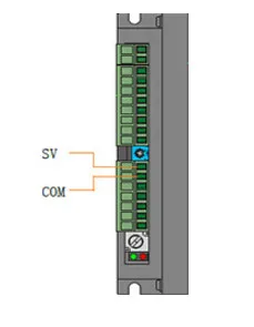
Driver interface and motor connection
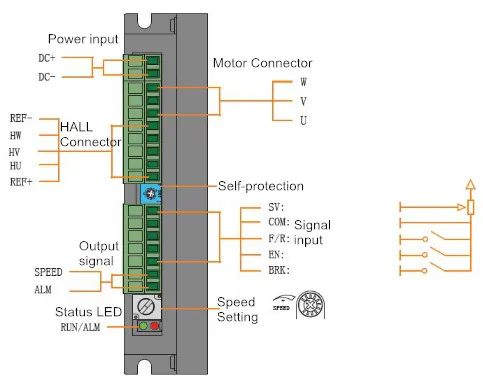
Signal | Terminals | Function |
Input | SV | 1.External potentiometer; 2.Input analog signal; 3.PWM pulse width. |
COM | Common port (0V reference level) | |
F/R | High level input the motor will rotates clockwise, low level input or when F/R and COM are connected, the motor will rotate anticlockwise | |
EN | High level input the motor will slowly stops, low level input or when EN and COM are connected, the motor runs | |
BRK | The motor brake stops when a high level is added or port suspension; the motor runs when the low level is added or EN and BRK are connected | |
Output | ALM | The fault output signal of the motor or drive is 5V under normal circumstances; the level is 0V when a fault occurs. |
SPEED | The output of speed is pulse frequency corresponding to the motor running. The terminal can be connected to upper computer |
Four speed regulation modes
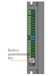
Build-in potentiometer RV
Rotate the RV knobs clockwise until a “click” sound, the motor starts to run. Rotate the RV knobs clockwise, the motor will accelerate. Rotate the RV knobs anticlockwise, motor speed will decrease, and the motor will stop until a "click" sound.
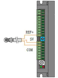
External potentiometer
Use a suitable potentiometer with a resistance value of 10KΩ, connect middle terminal with SV terminal, and the other two terminals are respectively connected with REF+ terminal and COM terminal.
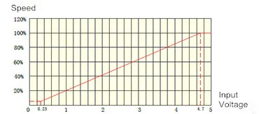
Input analog signal (0-5V)
When the input voltage is 0.25V, the motor speed is 5% of the maximum speed; When the input voltage is about 4.7V, the motor speed is the maximum value.
PWM pulse Width
Frequency: 1-3KHz Amplitude value: 5V
Pulse width: Adjust the duty ratio for speed regulation