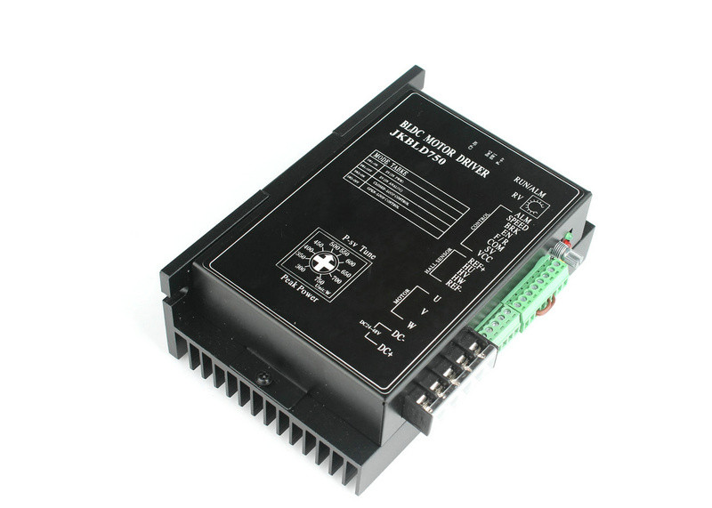
CNC Brushless DC Motor Driver JKBLD750 For 0W - 750W 1HP 3000RPM 48V BLDC Motor
Description:
The BLD750 BLDC motor drive is a high performance, cost-effective 3phase BLDC motor drive, which can provide power output Max 750VA.The design is based on advanced DSP technology and feature high torque, low noise, low vibration, PID speed loop, PID current loop, over current protection, over load protection and a combined use of manual speed adjustment and automatic speed adjustment.
Connection Definition:
| Mark | Definition |
| DC+/DC- | DC Power Input (DC24V~DC48V) |
| U,V,W | Motor Lead Wire |
| Hu,Hv,Hw | Hall Sensor Lead Wire |
| REF+ | Hall Sensor Power Supply + |
| REF- | Hall Sensor Power Supply - |
| VCC | External Potentiometer Power Supply ( Internal Power Supply Only) |
| SV | External Potentiometer ( No Connection When Adjusting Speed With Internal Potentiometer ) or Pulse Rate In Note① |
| COM | Common (Low Level/Ground) |
| F/R | Direction: Low Level/CCW High Level or No Connection/CW Note ② |
| EN | Enable: High Level/Stop Low Level/Run Note ② |
| BRK | Quick Brake: High Level/Stop Low Level/Run Note ② |
| SPEED | Speed Signal Output |
| ALARM | Alarm Signal Output |
Note①: Potentiometer/10KΩ or analog signal DC 0V~+5V (Change
internal switch J1/DC0-10V).Turn off the internal potentiometer RV
when using an external potentiometer to adjust the motor speed.
Note②:High level/5V (5mA)
Electrical Specifications:
| Parameter | Min | Rated | Max | Unit |
| Motor Hall Sensor Angle | 120°/240° | |
| DC Power Input | 18 | 48 | 50 | V |
| Drive Current Output | 0 | 25 | 45 | A |
| Suitable Motor Speed | 0 | | 20000 | rpm |
| Hall Sensor Voltage | 4.5 | 5 | 5.5 | V |
| Hall Sensor Current | | 20 | | mA |
| External Potentiometer | | 10K | | Ω
|
Peak Power Output Setting:
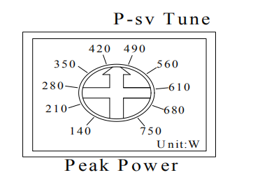
Note: To protect the motor, set the arrow number as the same as the motor nominated power. Whenever overload occurs the drive will turn out to be the protection mode.
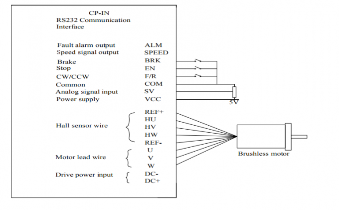
Connection:
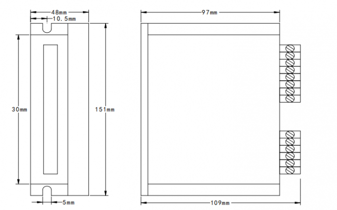
Mechanical Drawings:
Speed Adjustment Instruction:
Motor Speed Adjusted By The Internal Potentiometer RV:
SW1/ Off (Factory setting)
Motor Speed Adjusted By Analog DC 0V~+5V Input:
SW1/ Off (Factory setting) set J1 (internal) as (user Setting) RV—Turn Off
Motor Speed Adjusted By Analog DC 0V~+10V Input:
SW1/ Off (Factory setting) set J1 (internal) as  (user Setting) RV—Turn Off
Motor Speed Adjusted By Pulse Rate Input:
Pulse rate: 0K—3KHZ Speed linear modulation
Pulse amplitude: 5V Pulse duty ratio: 50%
SW1/ On (User setting) RV—Turn Off
J7 (Internal)/ Switch on with the jumper cap on J1 (User setting)
Motor Speed Quick Response Setting:
SW2/ On ( User setting): PID closed loop--quick speed response
SW2/Off (Factory setting): Open loop--Normal speed response
Motor Speed Signal Output:
Connecting SPEED and COM to get pulse output F=N*P/60
F—Pulse output frequency
P—Pole number of BLDC motor
Drive Alarm Output:
When drive alarm, it will break over with the port of COM and be low
level. The drive stop to work and alarm light run.
Lead Wire Connection: Take care of the sequence of U,V,W
Motor Parameter set by ICAN BLDD-01 (Optional) :
RS232 Communication Interface CP-in
The BLDD48-45A BLDC motor drive support RS232 communication Protocol to set motor run-up time, etc. When choose ICAN BLDD-01 as host controller, the operating process and instruction as below:
ICAN BLDD-01 Motor Setting Panel Operating Process:
Connect to CP-in (BLDD48-45A)
SW1/ Off (Factory setting) RV—Turn Off
BLDD-01 Parameter Setting Table:
| Function code | Mode | Setting range | Unit | Factory setting | Alteration |
| P000 | Control mode | 00 BLDD-01 control 01 None host control | | None Panel control | ★ |
| P001 | Panel setting speed | 0~Rated speed | RPM | | ★ |
| P002 | Run-up time | 0.1~9.9 | S | 0.2 | ★ |
| P003 | Motor pole number setting | 1~99 | Pole pairs | 4 | ★ |
| P004 | CW CCW | 01 CW 00 CCW | | 01 | ★ |
| P005 | | | | | Reserved |
| P006 | | | | | Reserved |
BLDD-01 Panel Setting Process:
1. Turn on the power supply, press <Set> to stop the motor
2. Press <▲> or <▼> to choose the mode you need (Press Esc return and motor running)
3. Press <Set> enter into parameter mode (Press Esc return and motor running)
4. Press <Set> to reserve, parameter stop to flash. Press <Esc> return and motor running.
Panel Protection Mode:
When the system running, panel nixie light shows Err×
Err0 represents Over-voltage or Over-temperature protection
Err1 represents Over-current protection
Err2 represents Hall sensor error protection
Motor Parameter set by other host controller:
BLDD48-45A Communication Protocol (RS232)
1. Communication Interface:
Asynchronous serial communication
Baud rate:2400
Start bit:1 bit
Stop bit:1 bit
Data bit:8 bits
Even/odd parity:none
Communication interface voltage:3.3V
2.Communication Protocol:
Function1:Motor speed controlled by drive BLD-750 itself
Communication format :“i”
Instruction:send a character
Function2:Motor speed controlled by host computer
Communication format:“o”
Instruction:send a character
Function3:Motor speed set by host computer
Communication format:“v”0X00,0X00
Instruction:send a character “v” then two hexadecimal numbers
the high 16bits,the low 16 bits
Function4:run-up time
Communication format:“y“ 0X00
Instruction:send “y“ then a hexadecimal number


-18x16.jpg)


